Friday, December 6, 2013

Dock: Day I've-Lost-Count


So, update on the last few weeks. A lot happened, so I'm just going to try to go in order. 

Basically, we took a crash course in mechanics trying to figure out if our idea of a cantilevered beam hanging over the side of the dock was even vaguely feasible and/or safe. Here are some beautiful pictures of that exceptionally long and painful experience:

The Original Plan

The pretty picture
The "hey professor, we don't know what we're doing"

Trying desperately to remember physics. And combine it with our math knowledge.
Let's be honest, we kinda just listened to Prof. Banzaert at this point.
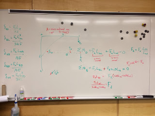
I thought I'd include a picture of the whole board because it makes us look smart.
Then we tried to remember geometry...and trig...it took us an embarrassingly long time to do this...
But...but...we can do multivariable calculus....usually...
We then changed the materials, type of beam (between tubes, pipes, and rods), and the measurements of the beams about a zillion times trying to find one that had a deflection percentage of less than 0.05% in all of the pieces of the beam. This took us approximately forever, and we couldn't find one that fit the criteria, so we concluded that the cantilevered beam, even with a support strut, was not a good option. Also, the support strut would have to be so across half of the beam, making it very difficult to shimmy along.

The diagram for this prototype, along with the anthropometric measurements we used to determine its size
The diagram for this prototype, drawn to scale
So we looked at some other options:


And we took a trip to a playground (for science!):

I was too tall to use the bar...
Pretend that that scarf is a metal pole.
And determined that having the vertical bar right in the middle of the horizontal bar would not really be a problem in terms of how easy or difficult it would be to shimmy across the bar. After a little bit of tinkering with our equations (read 2 hours), we determined that, with the right material, this idea would be feasible if we use 1.75" (diameter) "Easy-to-Weld Wear-Resistant 8620 Alloy Steel" rods and weld them together (yay!). The diameter was determined by a combination hand anthropometry statistics and Amy and me running around the library hanging off of random bars (and measuring them because we are just that scientific).

The funny part was that we didn't get any weird looks doing this... I don't know what that says about our college...
This makes it science!
 Unfortunately, the full size prototype will be very expensive, so we started building a prototype (complete with dock and wheelchair) with a 1/343 scale:

The diagram for our newest prototype, drawn to scale
Calculating the scale of our prototype
The first prototype
(made with random materials and very inexpert techniques, i.e. hot glue and smashing wire to bend it over)

The rod that we ordered to make our next prototype.
It is the same rod that we want to use for our full-size prototype, but at a 1/343 scale.
The diagram for the dock

The halfway-finished dock (to scale - we estimated the size of their dock)

Diagrams and calculations for the scale model of the wheelchair
The wheelchair model before printing
An Amy in her natural habitat.
We will be showing our finished scale prototype to Community Rowing to get feedback before we make the final purchase because we don't want to damage any of our expensive materials making a full size prototype before we are sure that the product will work and be useful. Also, in order to safely and securely attach the vertical pole to the dock, we will need to use a crane base, cost hundreds of dollars at least, so we are going to give our plans to CRI and see if they want to implement it.

Tuesday, November 5, 2013

CRI Day 6


Update: we will be working on both the issue of the fixed seat and the issue of transfer from wheelchair to shell.
Amy was still sick today and I didn't feel comfortable starting a new project regarding transfer without talking to her, so I worked on the erg chair project that we decided on when we visited CRI last week.
Basically, the rowers at CRI have this set-up for their ergs:


But they found that this sets the seat too high up for rowers to get the best draw angle--the height makes it so that they have to use a completely different set of muscles. The seat needed to be lower, which is why they had it upside down when we first visited them:


So the goal for today was to figure out how to adapt their existing hardware to be lower. CRI lent us a set of the connective parts of the erg and I started out the day by disconnecting the spacer 
from the connective plates, screws, and bolts. 


This is what I ended up with.
At this point, I was a little bit confused about how the connective pieces actually attached to the seat itself and thought that I would have to build a spacer between the connective plate and the seat to allow room for the bolts. 


I wasn't quite sure how to do this, however, so I decided to take some measurements and look more closely at pictures of the entire adaptive seat and connectors. I saw that the seat connects to the connective plate by having bolts or screws go through another plate.


So I figured that we will be able to just put the bolts through both plates, an idea that I will be testing when we go to CRI again on Friday.

Prototype #1
Things we should think about next (erg chair):
  • Does this design function correctly and solve the height problem?
  • Using this design, how quickly can an erg be changed from sliding to fixed?
  • How can this transformation process be speeded up?
  • Is there a different way of connecting the seat to the erg that does not include screw clamps, which take a relatively long time to screw in? Is this new way sufficiently strong to hold the seat securely onto the erg while taking the abuse of the rowers rowing?
Things to ask rowers/coaches at CRI:
  • Have them try to set it up. - see if they can figure it out, if they use it in an unexpected way, etc. - VIDEO them (do a time study)
  • Do you have any initial impressions or ideas about the prototype?
  • What works well about this device?
  • What does not work well about this device?
  • For transfer project: What type of shells do you use? (so we can find out what they are made of, their strengths, etc.)


klsjaklfkajkfj

Friday, November 1, 2013

CRI Day 5

Note: I missed a few blog posts, as Amy and I have mostly been posting on her blog (http://extd111-afeldman.blogspot.com/). We will be setting up a joint blog soon.

Anyway, Amy was sick today, so I started out the day working on our dock model. I was figuring out how to make the sides of the "tub" part of our "water elevator" model connect to each other. We were thinking about using magnets, just for our model, because it wouldn't work very well for the final dock. So I started by considering embedding a piece of metal in one piece of foamcore while having the magnet on the outside of the opposing piece of foamcore, but the magnets weren't strong enough for this to be a viable option. So I quickly moved on to embedding the magnet in the opposing piece of foamcore, which would put the magnets closer together.

The magnets and metal bars.


At this point, however, Professor Banzaert came over and suggested that I spend some time calculating the dimensions of the "tub" and the weight of the water we would be lifting in our elevator. It took me over an hour to find all of the measurements I needed, but I finally found them and did the calculations....

Just in case you can't read that: we would need to lift approximately 14.375 metric TONS. Even if we could figure out a way to do this, it would most likely not be at all affordable, so that idea was out...

Next up, working on our second semi-finalist: The Launching Pad

The Launching Pad idea was modeled after the EZ launch. The EZ launch was built for the far sturdier kayaks and canoes, so we will have to make some modifications for the more fragile rowing shells.
EZ Launch

Friday, October 25, 2013

Erg Chair: Day 2

We started off today planning to make more detailed diagrams and list the parts we needed in order of importance so that we could order them. Then we looked back at the pictures of the fixed erg seat that CRI already has...and we compared it to the pictures advertising the device...

These are the original pictures of the device at Community Rowing:


This is the picture from the product page:

As you can see, the product picture shows the moving seat still attached to the erg, with the fixed seat over it.  The attachment device (clamps) are also reversed from how Community Rowing has it installed. If they reversed their attachment, the adjustment screws would be on the bottom, which would potentially make it much easier to adjust... So our problem might already be solved...

Tuesday, October 22, 2013

Erg Chair: The 1st Official Day


    Amy and I started on our project for Community Rowing, which is to improve the fixed seats that they have for the adaptive rowers with limited lower body movement.
 
   So, we started out the day by going through the giant pile of brainstormed ideas that we generated during the last class. We then decided to focus on ways to fix the seat to the erg itself securely, while still making it easier to adjust in the horizontal direction.

   We started out looking at draw latches and tension latches (like the ones on jam jars) and the kind of pin locks that they use in weightlifting machines.

But first, we took a physics break and looked at the forces acting on the seat. (I even drew a very bad free body diagram!)

Then, Professor Banzaert directed us to the hardware website McMaster-Carr, where we found this gem:
Inline image 1
Anyway, after we recovered from this little dose of awesome, we finally found what we were looking for (sort of...): 
Inline image 1 
Eventually we decided that this might not be the best pin to use, so at this point we just know that we are going to be using a quick-release pin.

For adjusting the seat, we considered using a Telescoping Round-Hole Strut Channel

Then we realized that we would need to attach the channel and the tube to the chair and the erg itself, so that whole idea was out...

So we actually used our brains (whoa) and then we figured out a design that might work... It ended up basically being a combination of the ideas we brainstormed in the first place, we just took a long time to develop them.